Micromirror Oligo Array
- Texas Instruments - Creator of the micromirror array; overview of the technology and application in commercial digital projectors.
- NimbleGen - Company commercializing the maskless in situ oligo synthesis technology.
- Digital Optical Chemistry - Skip Garner's group at University of Texas Southwestern Medical that has a micromirror-based synthesizer set up. A good primer for the basic idea and system.
- Proligo LLC - German company selling Raydites®, the NPPOC photolabile phosphoramidites to be used in our system.
- PDMS Overview - A good overview page at the University of Wisconsin-Madison.
- Lipshutz, et al., 1998 - (The original?) Affymetrix paper describing the discriminating abilities of DNA oligo arrays (their GeneChip® product).
- Singh-Gasson, et al., 1999 - The Nature Biotech paper describing the maskless in situ synthesis system.
- McGall, et al., 1997 - Affymetrix paper describing the photodeprotection rates and step-wise synthesis efficiencies of MeNPOC phosphoramidites.
- Beier & Hoheisel, 2000 - Nucleic Acids Research paper describing the advantages of NPPOC, the next-generation photolabile protecting group.
Introduction
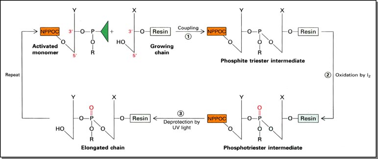
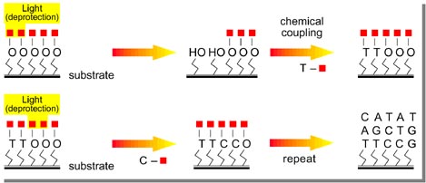
The process for 3'-5' chemical DNA synthesis using UV light for stepwise deprotection differs from standard acid deprotection only at that step. We thus use phosphoramidites protected at the 5' end by a photolabile NPPOC group instead of an acid labile dimethoxytrityl (DMT) group. The other steps (phosphoramidite activation, oxidation, etc.) are virtually identical: (figure modified from Stryer, 4th ed.):
Our Efforts
We've sketched out six major components to building our own micromirror system:
- Imaging hardware and optics geometry: from UV light source to image (ie., mask) reproduction on slide
- Flow cell: housing for slide / controlled environment for synthesis chemistry
- Reagent delivery system: for synthesis chemicals (can adapt old DNA synthesizer to our flow cell)
- Informatics: selection of oligo sequences, optimizing for subject-specific study (eg., sequence specificity for expression profiling)
- System integration: controller software orchestrating chemical delivery and oligo deprotection/mask projection
- Chemistry: functionalized glass support as substrate for oligo synthesis (e.g., NPPOC-PEG slides) and optimizing conditions for photodeprotection and monomer coupling
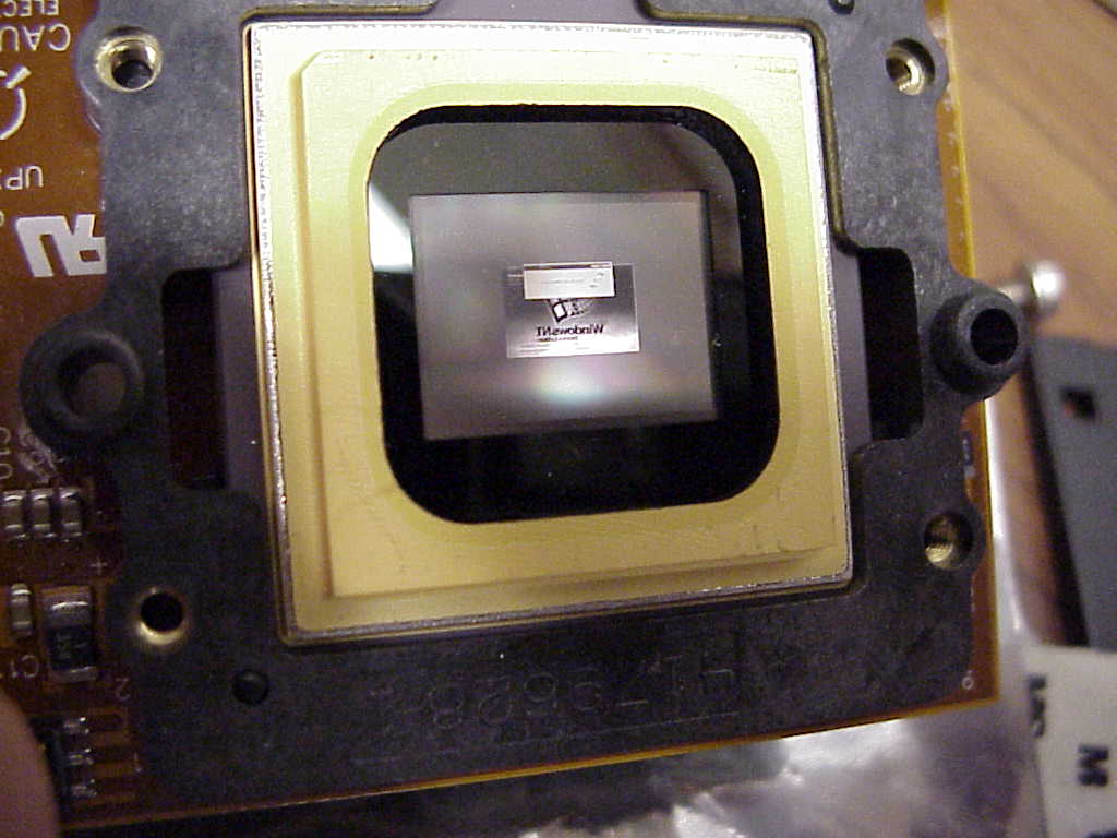
The development kit we purchased from TI was very straight forward to set up. It consists primarily of a commercial PC video card with flat panel direct digital-out (ie., no lossy digital-analog conversion) that interfaces with a second video driver card from TI. It thus requires 2 empty PCI slots. The TI video card then connects via SCSI III to an independently-powered formatter board, which piggybacks onto the micromirror unit. When powered up, the micromirror displays the reflection of whatever image is fed to your video board (remember to flip the switch to Run on the board, and plug in the power supply to the board). Here you see a mirror image of the Windows NT login screen:
Micromirror Duty Cycling: It was brought to our attention that the TI formatter board has a feature that "exercises" the micromirrors. Basically, if mirrors are unactivated for a long time, they will begin to stick. So, the formatter board will flip mirrors randomly to keep them "lubricated." This could have consequences for our stepwise coupling efficiency if features are randomly hit with UV light and deprotected. However, since the time constant for photodeprotection is on the order of seconds, the flipping speed of the mirrors is on the order of microseconds, and the duty cycle is infrequent enough that you do not observe speckling in commercial projectors, we reason that this won't have too much of an impact. However, we'll reserve judgment until we have some empirical data.
Optics
From looking inside a disassembled commercial projector, we determined that the plane of the projected image is parallel to the plane of the micromirror, and the light is incident to the mirror at about 30-45o.
Light Source: From research done in the Oriel catalog, we need:
- 350 W Hg lamp: lamp model #6286, socket adapter model #66161
- F/1 condenser, UV grade fused silica: model #66942
- Water filter, 1.5" series: model #61945
- Quick change filters: model #71260
- UV-pass filter, 360 nm: model #53410 (1" diameter), model #58650 (2" diameter)
- 500 W power supply: model #68920
- lamp housing
- rigid optical table
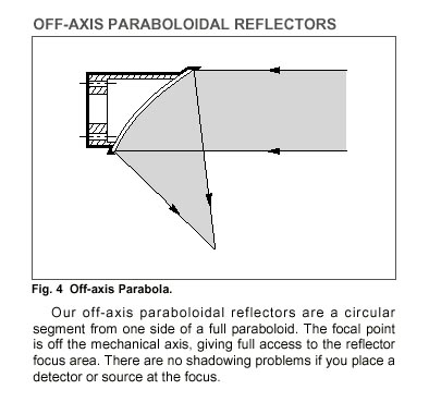
Projection: We can use a series of lenses (like in Garner's system) to focus the mask image onto the slide. However, as with Singh-Gasson, et al., we prefer a system of mirrors as more photon energy is generally transferred. Although this calls for a little more research, we are speculating that a single off-axis paraboloidal reflector would be able to both collect and focus the light rays coming off the micromirror, accomplishing the task of 2 lenses or 2 mirrors, as in the Singh-Gasson, et al. Offner relay:
Flow Cell: The design constraints for our single slide flow cell are:
- Material must be resistant to various organic solvents involved in DNA synthesis (mainly acetonitrile and I2 oxidizer)
- Will be maintained at a pressure between chemical stores and waste tank (Pchems > Pflowcell > Pwaste) for directed fluid flow
- Slide will be in anhydrous environment: material hopefully does not absorb and hold water (or the other reagents)
- Slide must be in rigid alignment with micromirror: material hopefully not too pliable
- Volume should be as small as possible without incurring depletion effects
| Chemical | Weight Before (g) | Weight After(g) | Change | Notes |
|---|---|---|---|---|
| ACN | 0.4485 | 0.4461 | 0.5% | 44 hrs, room temp |
| Cap A | 0.3597 | 0.3490 | 3.0% | 44 hrs, room temp |
| Cap B | 0.3772 | 0.3735 | 1.0% | 44 hrs, room temp |
| Oxidizer (0.05 M I2) | 0.3653 | 0.3855 | 5.5% | 44 hrs, room temp; stained orange |
| 0.45 M Tetrazole in ACN | 0.3440 | 0.3406 | 1.0% | 44 hrs, room temp |
| NH3OH | 0.3925 | 0.4101 | 4.5% | 42 hrs, room temp to 4.5 hrs, 65o |
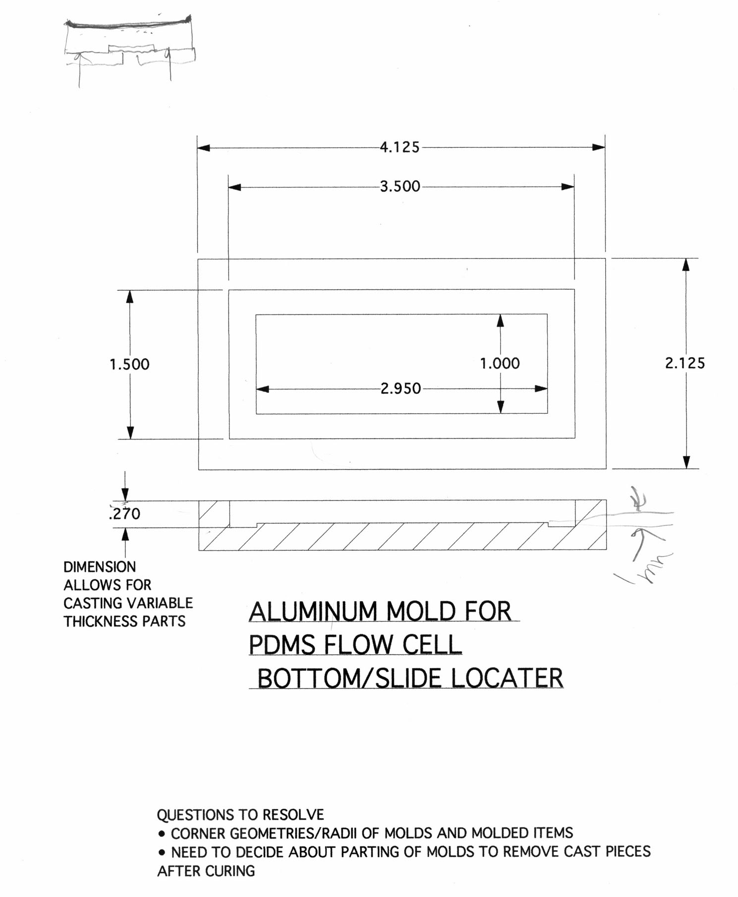
Here is a sketch and some vector drawings (courtesy of Jim Horn in the HMS Machine Shop):
 |
 |
 |
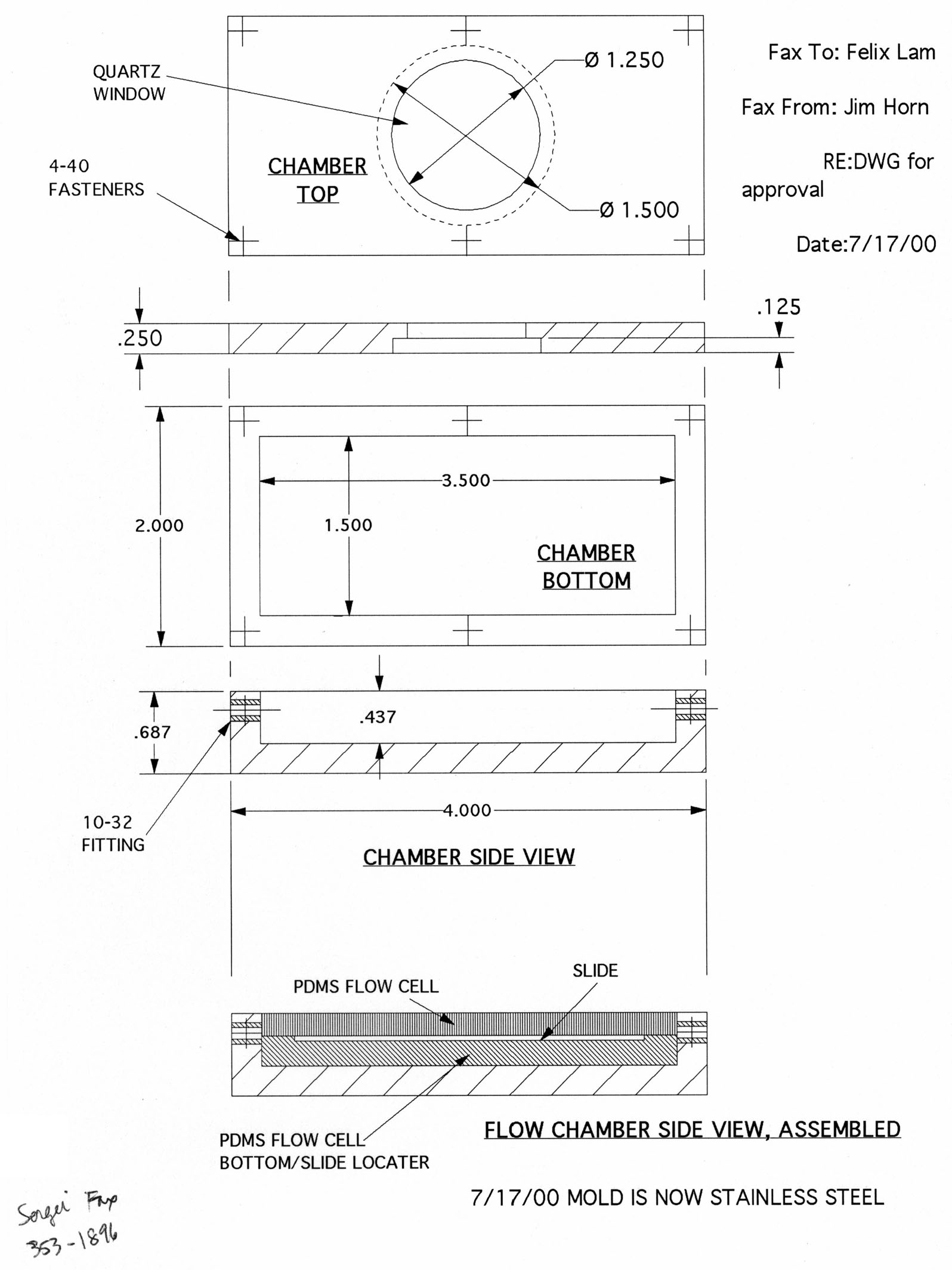 |
The near-final design consists of two outer metal pieces: flow chamber bottom, and flow chamber top with quartz window. The top is secured to the bottom with 6 screws and an O-ring in between them, forming a sealed chamber capable of withstanding huge pressures. Inside will be 3 PDMS pieces: a bottom piece with recessed slide holder, and two symmetrical side pieces which "clamp" down on the slide when the metal chamber top is screwed down. The geometry of the side pieces should afford good streamline flow (validating Bernoulli analysis should fluid variables be needed).
Since the drawings were made, we decided that aluminum (while easily machinable) would not be the best material for the flow chamber as it can be readily oxidized by I2. We then considered teflon; while also easily machinable, it is probably too soft to handle the shear stresses of the 6 metal screws. We finally considered stainless steel, which is more than mechanically sufficient. To test the chemistry requirement, we left a piece of polished stainless steel in the oxidizing solution for 40-50 hrs at room temp. In the end, there was less than 1% change in weight and no observable oxides on the surface.
End Lamvolvement
8/23/2000 - F.Lam